9.2. ADC Interface#
As discussed in Section 1.1.2, the XCZU48DR RFSoC device contains hardened data converter blocks and PLLs to support the ADCs (and DACs) on chip:
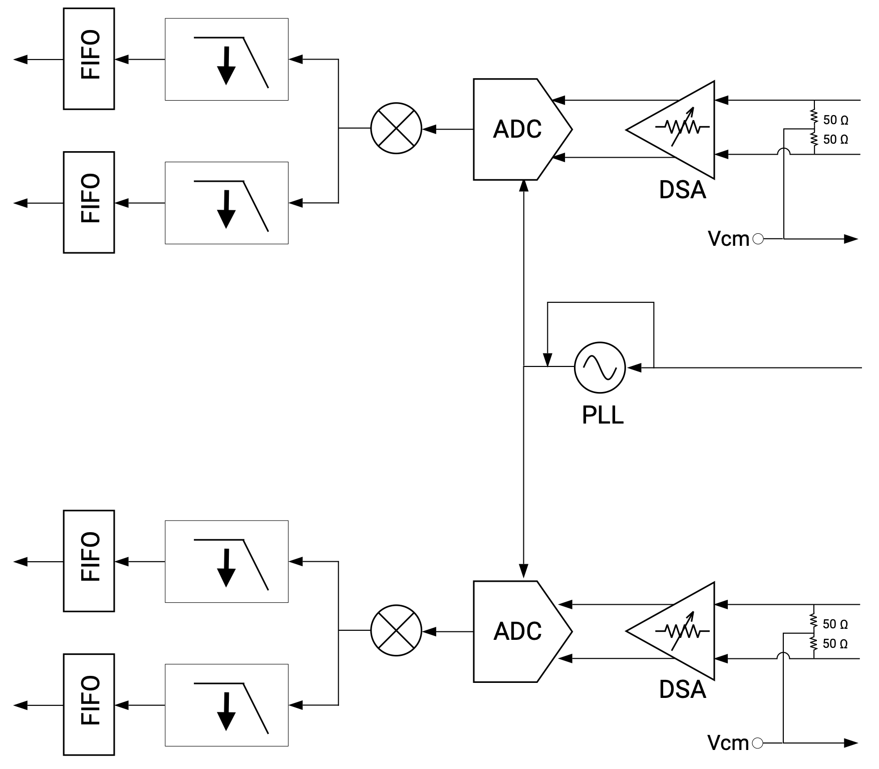
Fig. 9.1 Block diagram of an ADC tile with supporting data converter and PLL blocks on the XCZU48DR RFSoC device (image taken from [AMD-Xilinx23b])#
The ADC portion of the data converter block implements a number of DSP functions as shown in the figure below, including:
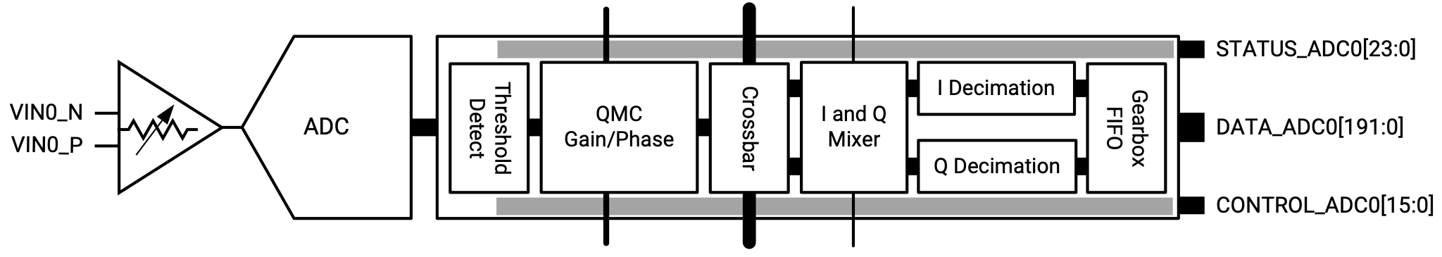
Fig. 9.2 Block diagram of the ADC portion of the data converter block on the XCZU48DR RFSoC device (image taken from [AMD-Xilinx23b])#
a signal magnitude detector,
a quadrature modulator correction (QMC) block,
a Digital Down Converter (DDC) that consists of
coarse frequency mixers and a numerically controlled oscillator (NCO), and
signal decimators with anti-aliasing filters.
All these DSP function components can be configured to implements standard Nyquist sampling (in the first Nyquist zone) of a real-valued baseband signal as discussed in Section 9.1.1 and second Nyquist-zone sampling of a real-valued bandpass signal as discussed in Section 9.1.3. Other modes of sampling, including sampling of complex-valued baseband and bandpass signals from the in-phase (I) and quadrature (Q) signal paths, can also be implemented using the hardened DSP functions.
The configuration of the DSP functions can be set when building the Vitis extensible platform using the RFDC IP block [AMD-Xilinx23b]. In
eee4511c_vitis_platform, the configuration is chosen to implement Nyquist sampling and frequency shifting of a real-valued bandpass signal centered at 98 MHz to give a complex-valued baseband signal. We will discuss some of the configuration settings below. See the course project for a more detailed discussion of the setup.The sampling rate of the ADCs is set based on the frequency of the stable reference clock input provided on the RFSoC 4x2 board. In
eee4511c_vitis_platform, it is set to \(4.9152\) Gsps. The I-Q mixer in the data converter block performs frequency shifting. Ineee4511c_vitis_platform, the I-Q mixer is configured to perform a frequency shift of -98 MHz, bringing the real-valued bandpass (centered at 98 MHz) signal sampled by the ADC to a complex-valued baseband signal. The DDC in the data converter block allows us to decimate the ADC output in order to equivalently lower the sampling rate (see my DSP notes for a more detailed discussion). Ineee4511c_vitis_platform, the decimation factor is set to 16, resulting in the sampling rate of \(307.2\) Msps reported in Section 1.3.3. The real part and imaginary part of the complex-valued baseband signal samples are separately provided as outputs of the data converter block.The ADCs on the XCZU48DR RFSoC device have a resolution of 14 bits (see Section 1.1.2). Each ADC sample is provided as a 16-bit fixed-point/integer value. The data converter block contains FIFOs to provide AXI4 stream (
axis) interfaces for our DSP kernel to access the streams of samples. Up to 12 samples (see the 192-bit wide data path in Fig. 9.2) can be packed together as the basic unit of anaxisstream to reduce the clock rate required to support theaxisinterface. Ineee4511c_vitis_platform, eight samples are packed into a chunk foraxisstreaming, requiring a clock rate of \(38.4\) MHz for theaxisinterface. The data converter block can be configured to provide a reference clock at that frequency to drive theaxisinterface as shown in Fig. 1.6.Below is a simple HLS kernel example that reads chunks of complex-valued samples from the
axisinterface of the data converter block and then stores them in the global memory:Kernel header (
stream_to_mem.h):#include <ap_fixed.h> #include <hls_stream.h> #include <complex.h> #include <array> #define MAX_N 8192 // Number of samples #define C 8 // Number of samples per chunk #define MAX_NC MAX_N/C // Basic ADC sample type typedef ap_fixed<16,1> rd_t; // Chuck type = array of C samples typedef std::array<rd_t,C> rc_t; typedef std::complex<rd_t> d_t; typedef std::array<d_t,C> c_t; extern "C" void top(hls::stream<rc_t> &s_in_real, hls::stream<rc_t> &s_in_imag, c_t *out, unsigned long N);
Kernel:
#include "stream_to_mem.h"
#include <assert.h>

void store(hls::stream<rc_t> &in_real, hls::stream<rc_t> &in_imag, c_t *out, unsigned long N) {
  assert(N%4==0);
  Write_Loop: for (unsigned long n=0; n<N; n++) {
#pragma HLS loop_tripcount max=MAX_NC
    rc_t real_chunk = in_real.read();
    rc_t imag_chunk = in_imag.read();
    c_t out_chunk;
#pragma HLS array_partition variable=real_chunk type=complete
#pragma HLS array_partition variable=imag_chunk type=complete
#pragma HLS array_partition variable=out_chunk type=complete
    Chunk_Loop: for (int j=0; j<C; j++) {
      out_chunk[j] = d_t(real_chunk[j], imag_chunk[j]);
    }
    out[n] = out_chunk;
  }
}

extern "C" {
void top(hls::stream<rc_t> &s_in_real, hls::stream<rc_t> &s_in_imag, c_t *out, unsigned long N) {
#pragma HLS interface mode=axis port=s_in_real depth=MAX_NC
#pragma HLS interface mode=axis port=s_in_imag depth=MAX_NC
#pragma HLS interface mode=m_axi port=out depth=MAX_NC
#pragma HLS dataflow
  store(s_in_real, s_in_imag, out, N/C);
}
}
The same technique of chunking using the
std::arrayclass in Section 8.3.2 is employed here to cast each block of eight 16-bit samples from the real (imaginary) stream of the data converter is casted into thestd::array<ap_fixed<16,1>,8>type object.Two
hls::streaminput arguments are employed in the top-level functiontop()to interface with the real and imaginaryaxissample streams provided by the data converter block.Chunks of complex-valued fixed-point samples are stored in the global memory as the output of the kernel.
Host code snippet:
// Compute the size of array in bytes
size_t size_in_bytes = NC*sizeof(c_t);
// Instantiate host input and output vectors
std::vector<c_t, aligned_allocator<c_t> > x(NC);

// These commands will allocate memory on the Device and link to host pointers
OCL_CHECK(err, cl::Buffer x_buf(context, CL_MEM_USE_HOST_PTR|CL_MEM_WRITE_ONLY, size_in_bytes, x.data(), &err));

unsigned long num_samps = N;
// set the kernel Arguments
OCL_CHECK(err, err = krnl.setArg(2, x_buf));
OCL_CHECK(err, err = krnl.setArg(3, num_samps));

// Call kernel to do filter
std::cout << "Getting signal sample from ADC ...\n";
// Launch the Kernel
OCL_CHECK(err, err = q.enqueueTask(krnl));
// Transfer output from gloabl to host memory
OCL_CHECK(err, err = q.enqueueMigrateMemObjects({x_buf}, CL_MIGRATE_MEM_OBJECT_HOST));
OCL_CHECK(err, err = q.finish());
std::cout << "Done getting signal sample from ADC.\n";

// save output samples to file
std::cout << "Writing data to signal.txt\n";
std::ofstream file;
file.open("signal.m");
file << "x=[" << std::endl;
for (int n=0; n<N; n++)
  file << x[n/C][n%C].real() << "+1j*(" << x[n/C][n%C].imag() << ")" << std::endl;
file << "];";
file.close();
Only the top-level function arguments of the output global memory buffer and the number of samples to capture are set in the host code.
Explicit connections of the
hls::streamarguments of the top-level function to theaxisinterfaces of the data converter block must be specified in the kernel configuration file in Vitis (see Course Project).If the HLS kernel and the data converter block’s
axisinterfaces are under different clock domains (e.g., ineee4511c_vitis_platform, the HLS kernel is drived by the \(200\) MHz platform clock while the data converter block’saxisinterface clock is at \(38.4\) MHz as discussed above), Vitis should automatically insert AXI4 stream clock converters to interface between the kernel andaxisinterfaces. However, this functionality does not seem to be correctly implemented in Vitis 2024.2 for some designs. To circumvent this bug, I have manually added the AXI4 stream clock converters ineee4511c_vitis_platformas shown:
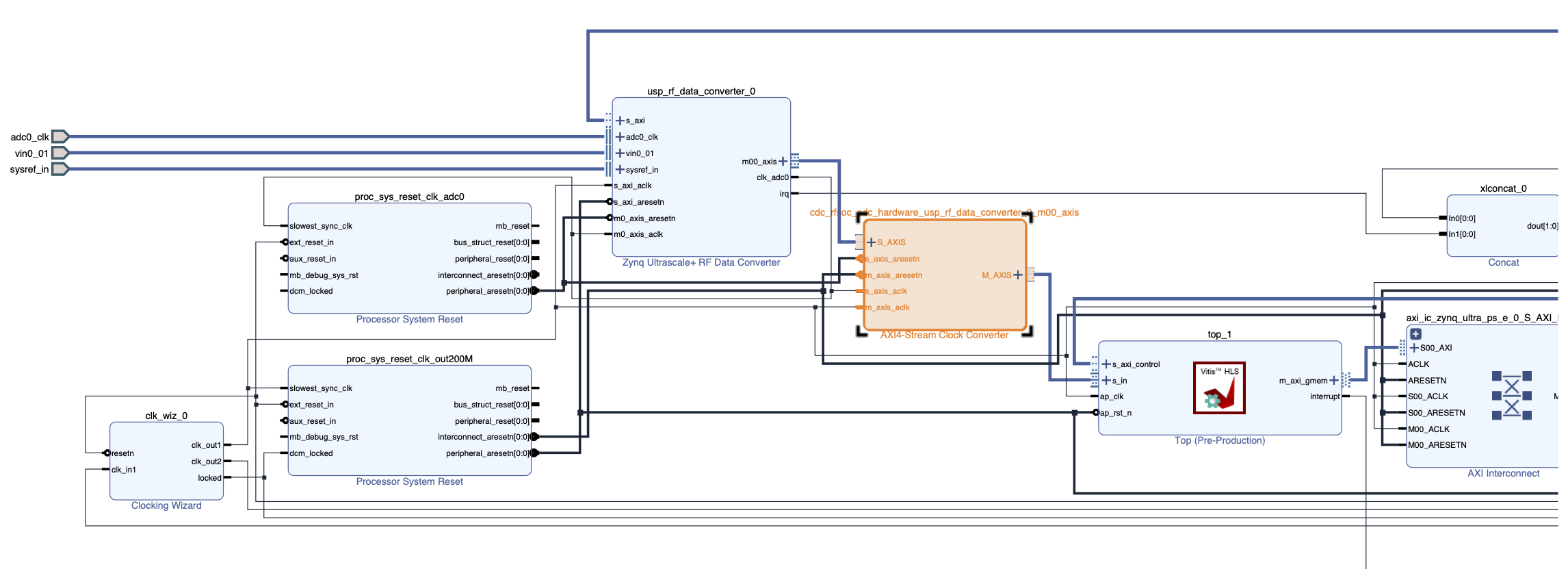
Fig. 9.3 Block diagram showing connection between the HLS kernel and the data converter’s
axisinterfaces ineee4511c_vitis_platform.#The same chucking approach can also be applied to any DSP kernel that is connected to the data converter block’s
axisinterfaces, using the complex-valued sample stream as a signal source. For example, one may modify the direct-form FIR filter implementation discussed in Section 7.2.1 as below to filter the complexed-valued samples directly from the data converter block:void fir(hls::stream<c_t> &in, hls::stream<cfil_t> &out, unsigned long numchunks) { dfil_t w[L] = {}; #pragma HLS array_partition variable=w type=complete chunk_loop: for (unsigned long n=0; n<numchunks; n++) { #pragma HLS loop_tripcount max=MAX_NUMBLKS*MDC cfil_t chunk_in = in.read(); cfil_t chunk_out; #pragma HLS array_partition variable=chunk_in type=complete #pragma HLS array_partition variable=chunk_out type=complete each_chunk: for (int j=0; j<C; j++) { #pragma HLS unroll factor=2 shift_loop: for (int k=L-1; k>0; k--) { #pragma HLS unroll w[k] = w[k-1]; } // Read in new chunk from in w[0] = chunk_in[j]; // Calculate output sample dfil_t y = dfil_t(0,0); //#pragma HLS bind_op variable=y op=mul impl=fabric latency=1 fir_loop: for (int k=0; k<L; k++) { #pragma HLS unroll y += b[k]*w[k]; } chunk_out[j] = y; } // Write to out out.write(chunk_out); } }
The type
dfil_tis a complex-valued fixed-point type for internal filter operations, similar tod_tabove but with perhaps a larger bitwidth for finer precision. The typecfil_tis simply a chunk forCdfil_tsamples, i.e.,std::array<d_t,C>.The loop
each_chunkis unrolled with a factor of 2 to achieve a tradeoff between throughput and PL resource usage.It can be verified from Vitis that the throughput for this FIR filter implementation is slightly above 2 samples per clock cycle. At the platform clock rate of \(200\) MHz, this translates to higher \(400\) Msps, high enough to support real-time processing of the stream of samples at the rate of \(307.2\) Msps.