7.1. Block Diagram & Signal Flow Graph#
7.1.1. Block Diagram#
All FIR and IIR filters can be constructed using the following three basic components:
Two-input adder:
\[\begin{align*} & x_2[n] \\ &\,\big\downarrow \\[-5pt] x_1[n] \longrightarrow & \!\bigoplus \!\!\longrightarrow x_1[n] + x_2[n] \end{align*}\]Scalar multiplier:
\[\begin{align*} & \,a \\ &\,\big\downarrow \\[-5pt] x[n] \longrightarrow & \!\bigotimes \!\!\longrightarrow ax[n] \end{align*}\]Unit delay:
\[\begin{align*} x[n] \longrightarrow & \!\boxed{z^{-1}_{}} \!\!\longrightarrow x[n-1] \end{align*}\]The construction of an FIR/IIR filter using these three basic component is often expressed in the form of a block diagram.
7.1.2. Signal Flow Graph#
The block diagram of an FIR/IIR filter can be represented by a signal flow graph (SFG). It is often more convenient to draw the SFG of a higher-order FIR/IIR filter than the block diagram representation.
The SFG of a filter is a (edge-)weighted directed graph \(G=(V,E)\) consisting of:
a set \(V\) of vertices that are signals generated in the block diagram of the filter,
a set \(E\) of edges, each of which is an ordered pair of vertices showing the direction of the signal flow,
at least one source vertex in \(V\) with no incident edges, and
at least one sink vertex in \(V\) with no emanating edges.
In addition, the vertices and the edges must satisfy the following conditions:
Each edge is associated with a gain factor (weight) that is either a scalar constant or \(z^{-1}\). The gain factor is applied to the first signal (vertex) to obtain the second signal (vertex) of the edge. If no gain factor is specified, the default value of \(1\) applies. For example, the edge \((w_1,w_2)\) with a gain factor \(z^{-1}\) means \(W_2(z) = z^{-1} W_1(z)\) in the \(z\)-domain, or equivalently \(w_2[n] = w_1[n-1]\) in the time domain. For convenience, we may write the edge as \((w_1, w_2; {z^{-1})}\) and draw it as \(\bigcirc\kern-7.5pt\vcenter{\tiny w_1} \!\xrightarrow{~z^{-1}~}\!\!\bigcirc\kern-7.5pt\vcenter{\tiny w_2}~\).
The signal associated with a vertex is the “output” signal in the sense that it is the sum of the incident signals to the vertex. For example, consider that the two unit-weighted edges \((w_1,w_3)\) and \((w_2,w_3)\), and that the signal \(w_3\) has only \(w_1\) and \(w_2\) as its incident signals. Pictorially,
\[\begin{align*} & \!\bigcirc\kern-7.5pt\vcenter{\tiny w_1}\\[-5pt] & \big\downarrow \\[-5pt] \bigcirc\kern-7.5pt\vcenter{\tiny w_2}\!\!\longrightarrow & \!\bigcirc\kern-7.5pt\vcenter{\tiny w_3}\!\longrightarrow \end{align*}\]This means \(w_3[n] = w_1[n]+w_2[n]\) in the time domain, or equivalently \(W_3(z) = W_1(z)+W_2(z)\) in the \(z\)-domain.
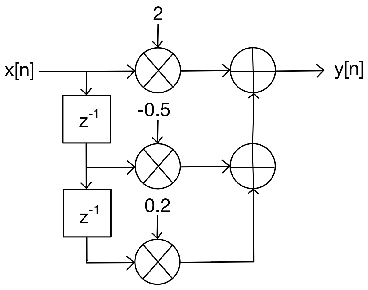
The SFG of the FIR filter depicted in Fig. 7.1 is:
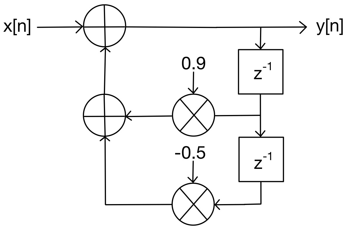
\[\begin{align*} \!\bigcirc\kern-6.5pt\vcenter{\tiny x} \longrightarrow & \!\bigcirc\!\!\xrightarrow{\hspace{10pt}{\scriptsize 2}\hspace{10pt}}\!\!\bigcirc \!\!\longrightarrow\!\!\bigcirc\kern-6.5pt\vcenter{\tiny y} \\[-0pt] {\scriptsize z^{-1}} & \Big\downarrow \hspace{25pt} \Big\uparrow \\[-10pt] &\!\bigcirc\!\!\xrightarrow{\hspace{5pt}{\scriptsize -0.5}\hspace{5pt}}\!\!\bigcirc \\[-0pt] {\scriptsize z^{-1}} & \Big\downarrow \hspace{25pt} \Big\uparrow \\[-10pt] &\!\bigcirc\!\!\xrightarrow{\hspace{8pt}{\scriptsize 0.2}\hspace{8pt}}\!\!\bigcirc \end{align*}\]The SFG of the IIR filter depicted in Fig. 7.2 is:
\[\begin{align*} \!\bigcirc\kern-6.5pt\vcenter{\tiny x} \longrightarrow & \!\bigcirc\!\!\xrightarrow{\hspace{12pt} \hspace{12pt}}\!\!\bigcirc \!\!\longrightarrow\!\!\bigcirc\kern-6.5pt\vcenter{\tiny y} \\[-0pt] & \Big\uparrow \hspace{25pt} \Big\downarrow {\scriptsize z^{-1}} \\[-10pt] &\!\bigcirc\!\!\xleftarrow{\hspace{8pt}{\scriptsize 0.9}\hspace{8pt}}\!\!\bigcirc \\[-0pt] & \Big\uparrow \hspace{25pt} \Big\downarrow {\scriptsize z^{-1}} \\[-10pt] &\!\bigcirc\!\!\xleftarrow{\hspace{5pt}{\scriptsize -0.5}\hspace{5pt}}\!\!\bigcirc \end{align*}\]


