6.2. Pole-Zero Placement#
From Section 6.1.2, we see that the magnitude and phase responses of any causal, stable FIR (IIR) filter can be decomposed into those of first-order systems, specified by the poles and zeros of the FIR (IIR) filter. Thus, it is necessary to study the magnitude and phase responses of first-order systems in detail.
There are two types of causal, stable first-order systems:
first-order FIR filter: \(\displaystyle H(z) = 1 - cz^{-1}\)
first-order IIR filter: \(\displaystyle H(z) = \frac{1}{1 - cz^{-1}}\) where \(|c| < 1\).
Here, we focus on investigating the magnitude and phase responses as functions of the parameter \(c\), i.e., the zero (pole) of the first-order FIR (IIR) filter.
Note also that the magnitude (phase) response of the first-order IIR filter is simply the reciprocal (negation) of that of the first-order FIR filter (if \(|c| <1\)). Hence, it suffices to consider only the first-order FIR filter.
Write \(c=re^{j\phi}\) where \(r=|c|\) and \(\phi = \angle c\). Then \(H(e^{j\hat\omega}) = 1 - re^{-j(\hat\omega - \phi)}\), and
\[\begin{align*} |H(e^{j\hat\omega}) | &= 1 + r^2 - 2r\cos(\hat\omega - \phi) \\ \angle H(e^{j\hat\omega}) &= \text{arctan2} \left( r\sin(\hat\omega - \phi), 1- r\cos(\hat\omega - \phi) \right). \end{align*}\]For \(0<r<1\), the plots of the magnitude response \(|H(e^{j\hat\omega})|\) and phase responses \(\angle H(e^{j\hat\omega})\) look like the following figures:
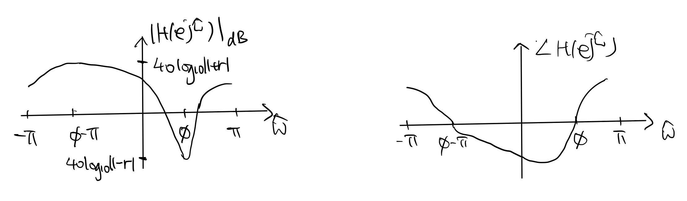
In particular, \(|H(e^{j\hat\omega})|\) reaches its maximum and minimum at \(\hat\omega = \phi-\pi\) and \(\hat\omega=\phi\), respectively.
From the plots above, we may conclude:
For the first-order FIR filter, \(\phi\) determines the frequency of the dip (minimum) in \(|H(e^{j\hat\omega})|\) and \(r\) determines the “sharpness” of the dip.
For the first-order IIR filter, \(\phi\) determines the frequency of the peak (maximum) in \(|H(e^{j\hat\omega})|\) and \(r\) determines the “sharpness” of the peak.
We may also obtain a simple geometric viewpoint for the first-order FIR filter. Rewrite the magnitude and phase responses as:
\[\begin{align*} |H(e^{j\hat\omega}) | &= | e^{j\hat\omega} - r e^{j\phi} | \\ \angle H(e^{j\hat\omega}) &= \angle \left( e^{j\hat\omega} - r e^{j\phi} \right) - \hat\omega. \end{align*}\]Now, consider the phasor diagram below that shows the relationship between the phasors \(e^{j\hat\omega}\), \(r e^{j\phi}\), and \(e^{j\hat\omega}-r e^{j\phi}\):
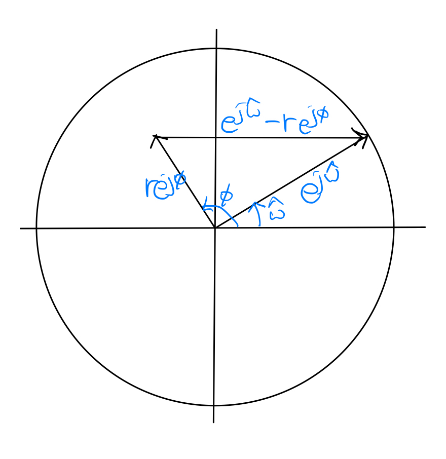
Note that \(|H(e^{j\hat\omega}) |\) is given by the length of the phasor \(e^{j\hat\omega}-r e^{j\phi}\) and \(\angle H(e^{j\hat\omega})\) is given by the difference between the angle of \(e^{j\hat\omega}-r e^{j\phi}\) and that of the phasor \(e^{j\hat\omega}\). Hence, sketches of the magnitude and phase responses can be easily obtained by tracing the phasor \(e^{j\hat\omega}-r e^{j\phi}\) in the figure above as \(e^{j\hat\omega}\) rotates.
After the magnitude and phase responses of the first-order components are understood, the magnitude and phase responses of the general FIR/IIR filter can then be constructed from the first-order responses using (6.2). Design of the filter can also be decomposed into the design of the first-order components, which are specified by the locations of the poles and zeros. Hence, by an appropriate placement of the poles and zeros of an FIR/IIR filter, we can obtain the desired magnitude and phase responses.