rfsoc4x2
A Vitis Extensible Platform with a single ADC for RFSoC4x2 (Vitis 2023.1 Classic IDE)
This is my second experiment with the RFSoC4x2 board. The goal is to build a simple Vitis extensible platform that supports pulling samples from one ADC of the ZU48DR device on board.
Step 0: Install the RFSoC4x2 board files
If not already installed, follow Steps 0.1 and 0.2 in the previous experiment to install the RFSoC board files. There is no need to install the Xilinx’s device tree repo and the ZYNQMP common image here. We will use Petalinux to generate a new image and a device tree.
Step 1: Create a Vivado Hardware Design
- Download the TCL script rfsoc_adc_hardware.tcl to
~/workspace. - Open Vivado and source the TCL script a TCL shell, or simply do
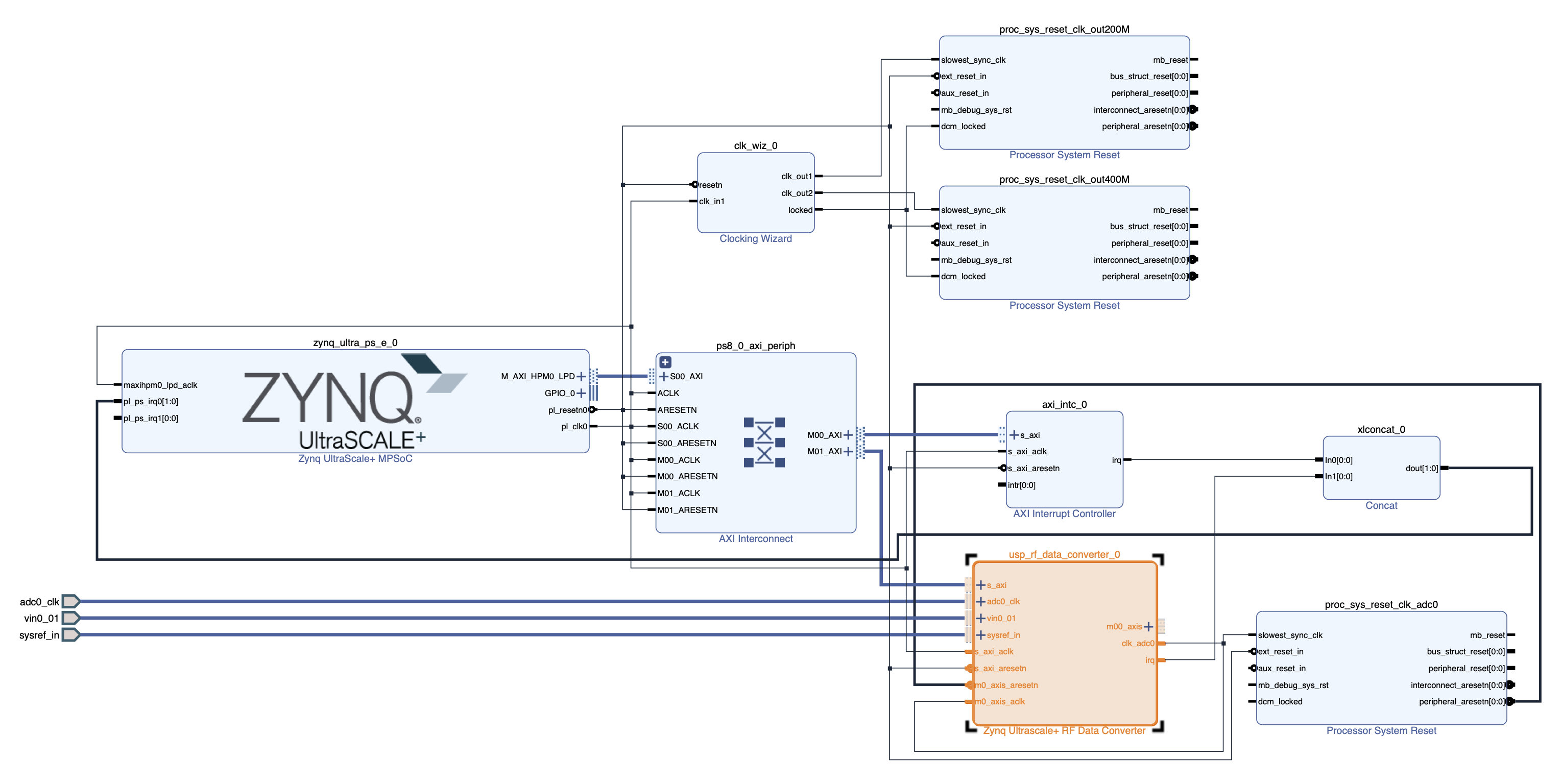
vivado -source rfsoc_adc_hardware.tclto generate the following block design:
 which adds an RF Data Converter IP to a slightly modified version of the hardware design in Vitis Platform Creation Tutorial for
ZCU104-Step 1.
which adds an RF Data Converter IP to a slightly modified version of the hardware design in Vitis Platform Creation Tutorial for
ZCU104-Step 1.- The Vivado project is named
rfsoc_adc_hardware. - ADC-D (ADC0 on tile 224) on the RFSoC4x2 board is enabled with sampling rate set to 2.4576 GSps.
- The Vivado project is named
- Export the platform
rfsoc_adc_hardware.xsafor both hardware and hardware emulation.
Step 2: Use Petalinux to create boot files, device tree file, linux image, rootfs, and sysroot
- Create a Petalinux project:
cd ~/workspace petalinux-create -t project --template zynqMP -n rfsoc-linux cd rfsoc-linux - Enter the hardware plotform
rfsoc_adc_hardware.xsaand select EXT4 for rootfs:petalinux-config --get-hw-description=../rfsoc_adc_hardware/rfsoc_adc_hardware.xsa- Select Image Packaging Configuration->Root filesystem type->EXT4
- Exit and save configuration
- Add relevant libraries to rootfs:
- Add the following line to
~/workspace/rfsoc-linux/project-spec/meta-user/conf/user-rootfsconfig:CONFIG_rfdcto allow including the
rfdclibrary (we don’t use it in this experiment though) - Run
petalinux-config -c rootfs - Select user packages->rfdc
- Select
xrt:- Petalinux Package Groups->packagegroup-petalinux-vitis-acceleration-essential->packagegroup-petalinux-vitis-acceleration-essential
- Petalinux Package Groups->packagegroup-petalinux-vitis-acceleration-essential->packagegroup-petalinux-vitis-acceleration-essential-dev
- Select
libmetal(mostly forrfdc):- Petalinux Package Groups->packagegroup-petalinux-openamp->packagegroup-petalinux-openamp
- Petalinux Package Groups->packagegroup-petalinux-openamp->packagegroup-petalinux-openamp-dev
- Select Python (to run some PYNQ scripts later):
- Petalinux Package Groups->packagegroup-petalinux-python-modules->packagegroup-petalinux-python-modules
- Petalinux Package Groups->packagegroup-petalinux-python-modules->packagegroup-petalinux-python-modules-dev
- Select
opensshfor convenience:- Filesystem Packages->console->network->openssh->openssh, openssh-ssh, openssh-sshd, openssh-scp
- Select Image Features->package-management and Image Features->debug-tweaks
- Select any other packages as wish
- Exit and save
- Add the following line to
- Configure the Linux kernel:
petalinux-config -c kernel- Allow user-mode SPI device driver support:
- Select Device Drivers->SPI support->User mode SPI device driver support (select the * mark)
- Exit and save
- Allow user-mode SPI device driver support:
- Add device tree descriptions to enable access to the reference clock chips (LMK04828 and LMX2594) via SPI:
- Add the following lines to
~/workspace/rfsoc-linux/project-spec/meta-user/recipes-bsp/device-tree/files/system-user.dtsi:/include/ "system-conf.dtsi" / { chosen { bootargs = " earlycon console=ttyPS0,115200 clk_ignore_unused root=/dev/mmcblk0p2 rw"; stdout-path = "serial0:115200n8"; }; }; &spi0 { lmk@0 { compatible = "ti,lmk04828"; reg = <0x0>; spi-max-frequency = <500000>; num_bytes = <3>; }; lmxdac@1 { compatible = "ti,lmx2594"; reg = <0x1>; spi-max-frequency = <500000>; num_bytes = <3>; }; lmxadc@2 { compatible = "ti,lmx2594"; reg = <0x2>; spi-max-frequency = <500000>; num_bytes = <3>; }; };
- Add the following lines to
- Build the image and sysroot:
petalinux-build petalinux-build --sdk cd images/linux ./sdk.sh -d .- The boot files, device tree file, kernel image, and the EXT4 rootfs are generated in
~/workspace/rfsoc-linux/images/linux/. The sysroot is in~/workspace/rfsoc-linux/images/linux/sysroots/cortexa72-cortexa53-xilinx-linux.
- The boot files, device tree file, kernel image, and the EXT4 rootfs are generated in
Step 3: Create a Vitis Platform
- Create a Vitis Platform project:
- Start
xsct:cd ~/workspace xsct - Once in the
xsctterminal, execute the following commands to create a Vitis platform project:setws . platform create -name rfsoc_adc_vitis_platform \ -desc "A Vitis extensible platform with 1 ADC for the RFSoC4x2 board" \ -hw rfsoc_adc_hardware/rfsoc_adc_hardware.xsa \ -hw_emu rfsoc_adc_hardware/rfsoc_adc_hardware.xsa \ -no-boot-bsp -out . domain create -name xrt -proc psu_cortexa53 -os linux \ -arch {64-bit} -runtime {ocl} -bootmode {sd} platform write platform generate exitThe platform project is now created in
~/workspace/rfsoc_adc_vitis_platform.
- Start
- Copy
system.dtband boot files from the image generated by Petalinux in Step 2 above:- Make the following two directories for convenience:
cd rfsoc_adc_vitis_platform mkdir boot fat32 - Copy
system.dtband other boot files to the directories:cp ~/workspace/rfsoc-linux/images/linux/system.dtb boot cp ~/workspace/rfsoc-linux/images/linux/system.dtb fat32 cp ~/workspace/rfsoc-linux/images/linux/boot.scr fat32 cp ~/workspace/rfsoc-linux/images/linux/bl31.elf boot cp ~/workspace/rfsoc-linux/images/linux/u-boot.elf boot
- Make the following two directories for convenience:
- Build the Vitis platform:
- Open up the Vitis GUI:
vitisIf the platform project doesn’t show up in the Explorer window, either go to Vitis->XSCT Console to open up an xsct console and type the following command:
importprojects rfsoc_adc_vitis_platformor go to File->Import… to import the platform project. The platform project created above should now show up in the Explorer window.
- Set the platform parameters:
- Open
platform.sprfrom the Explorer window (right-click->Open) - Set the paths to
fsbl.elfandpmufw.elf:FSBL: Click theBrowsebutton to select~/workspace/rfsoc-linux/images/linux/zynqmp_fsbl.elfPMU Firmware: Click theBrowsebutton to select~/workspace/rfsoc-linux/images/linux/pmufw.elf
- Select
xrtin the opened tab in the main window - Under
Domain:xrtfield:Bif File:Click downarrow in theBrowsebutton to selectGenerate Bif.Boot Components Directory:Click theBrowsebutton to select~/workspace/rfsoc_adc_vitis_platform/boot.FAT32 Partition Directory:Click theBrowsebutton to select~/workspace/rfsoc_adc_vitis_platform/fat32.Display Name:Change as wish.Description:Change as wish.- Leave
Linux Rootfs:andSysroot Directory:empty. - Build the platform by click the :hammer: button on the tool bar. After the build, the built Vitis platform is in~/workspace/rfsoc_adc_vitis_platform/export/rfsoc_adc_vitis_platform. - Fix thelinux.biffile:
- Select and open the
rfsoc_adc_vitis_platform/export/rfsoc_adc_vitis_platform/sw/rfsoc_adc_vitis_platform/boot/linux.biffile from the Explorer. - Change the two lines from:
[bootloader] <fsbl.elf>
[pmufw_image] <pmufw.elf>
to
[bootloader] <rfsoc_adc_vitis_platform/boot/fsbl.elf>
[pmufw_image] <rfsoc_adc_vitis_platform/boot/pmufw.elf>
- Open up the Vitis GUI:
Step 4: Test the Vitis Platform
- Create a new Vitis application project from template:
- Add Vitis example templates:
- Go to Vitis->Examples… to install example templates
- Click the
Downloadbutton to install the templates from the Vitis Accel Examples Repository - Only need to do this once
- Go to File->New->Application Project… to create a new application project:
- Select the
rfsoc_adc_vitis_platformcreated in Step 3. If the platform doesn’t show up as a choice, you can press the + button to add it. Press theNext>button. - Name the project
test_adc. Press theNext>button. - Under
Application settingsfield:Sysroot path:Click theBrowsebutton to select~/workspace/rfsoc-linux/images/linux/sysroots/cortexa72-cortexa53-xilinx-linux.Root FS:Click theBrowsebutton to select~/workspace/rfsoc-linux/images/linux/rootfs.ext4.Kernel Image:Click theBrowsebutton to select~/workspace/rfsoc-linux/images/linux/Image.- Press the
Next>button.
- Select the
- Select Acceleration templates with PL and AIE accelerators->Host Examples->Data Transfer (C) to finish up the application project creation step.
- Add Vitis example templates:
- Modify the kernel and host source codes and build the project:
- Under the Explorer window, replace the file
test_adc_kernels/src/dummy_kernel.cppin the template with thisdummy_kernel.cpp. - Replace the file
test_adc/src/host.cppfile in the template with thishost.cpp. - Specify
v++linker connectivity:- Open
test_adc_system_hw_link/test_adc_system_hw_link.prjfrom the Explorer - Under Hardware Functions, right-click
dummy_kerneland select Edit V++ Options… - Add the following lines to the
V++ configuration settingsfield:[clock] id=2:dummy_kernel_1 [connectivity] stream_connect = RFDC_AXIS:dummy_kernel_1.s_inClick the
Appy and Closebutton
- Open
- Build:
- Open
test_adc_system.sprjfrom the Explorer - Select Hardware for Active build configuration (located at upper right hand corner)
- Add
--package.no_imageto thePackaging optionsfield to turn off generating a disk image - Click the :hammer: button on the tool bar to build the project
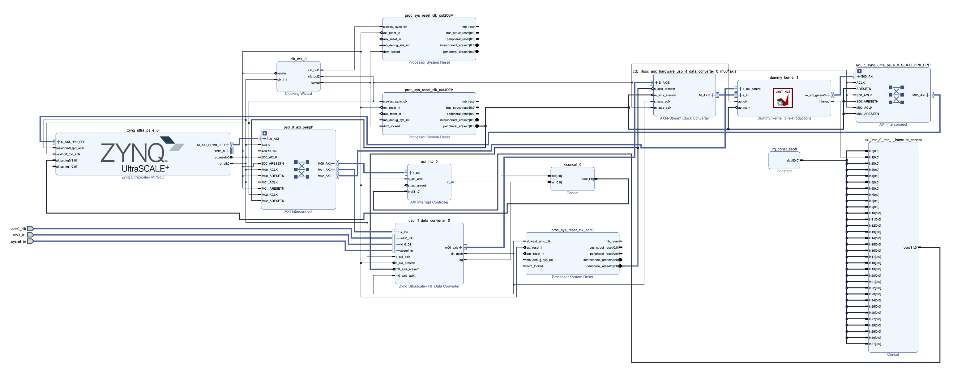
- The following block design is generated by Vitis:

- Open
- Under the Explorer window, replace the file
- Boot up the RFSoC board from an SD card:
- Insert the SD card into a card reader on a Linux machine. Check its device name:
lsblk -r -OFor example, my SD card is
/dev/sda. - Follow these steps to create a boot partition (FAT32) and a root partition (EXT4) on
/dev/sda. - Write the rootfs to the root (EXT4) partition:
sudo dd if=~/workspace/rfsoc-linux/images/linux/rootfs.ext4 of=/dev/sda2 bs=1M sudo resize2fs /dev/sda2 - Mount the boot (FAT32) partition:
cd ~/workspace mkdir mnt sudo mount -t vfat /dev/sda1/ mnt - Copy boot files, bit file, and executable to the SD card:
cp ~/workspace/test_adc_system/Hardware/package/sd_card/* mnt/ sudo umount mnt - Put the SD card into the microSD slot of the RFSoC4x2 board.
Use a USB cable to connect the Linux host to the JTAG/UART port on the RFSoC4x2 board.
Also connect the Ethernet port to a DHCP server if available.
On the host, run to connect to the UART port (install
picocomif needed):sudo picocom -b 115200 /dev/ttyUSB1Boot up the RFSoC4x2 board.
- Log in as
root(default password isroot, remember to change it after logging in). Doifconfigto check the IP address. With the IP address, can alsosshin asroot. Petalinux also creates a sudoer with loginpetalinux, whose passwd is set by the user when logging in the first time.
- Insert the SD card into a card reader on a Linux machine. Check its device name:
- Configure and turn on the reference clock chips (LMK04828 and LMX2594) via SPI:
scpthis python package filexrfclk-2.0.tar.gz(I hacked out from the RFSoC-PYNQ distribution) to say/home/root/on the RFSoC board.- Install the Python package on the board:
python -m pip install /home/root/xrfclk-2.0.tar.gz scpthis python scriptset_ref_clocks.pyto say/home/root/and then run it:python /home/root/set_ref_clocks.pyto turn on the reference clocks.
- Run the
test_adcapp to grab samples from the ADC:cd /run/media/boot-mmcblk0p1/ ./test_adc dummy_kernel.xclbinIf the app runs properly, should see the following printout:
Found Platform
Platform Name: Xilinx
INFO: Reading dummy_kernel.xclbin
Loading: 'dummy_kernel.xclbin'
Trying to program device[0]: edge
Device[0]: program successful!
Reading data from device
Writing data to wave.txt
The samples are stored in the file
wave.txt.Here is an example plot of the captured samples when a 2 MHz sinusoid is fed to the ADC-D SMA connector:
